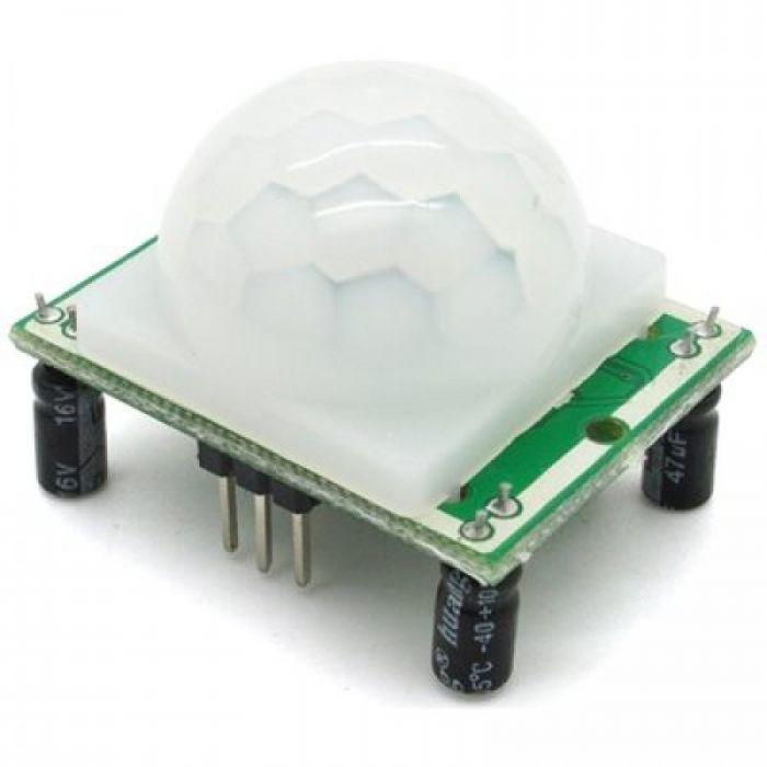
PIR sensor

NodeMCU
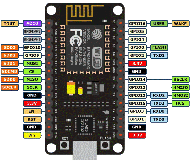
Pin Configuration
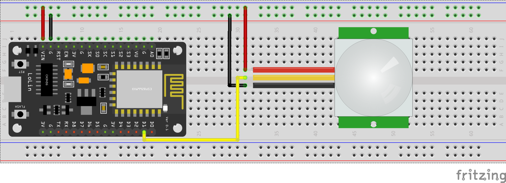
int PIR = D1;
void setup() {
 pinMode(PIR,OUTPUT);      // PIR SENSOR AS INPUT DEVICE
 Serial.begin(9600);       // 9600 BITS TRANFERING TO PC PER SECOND
}

void loop() {
  if(digitalRead(PIR) == HIGH){
     Serial.println("Motion Detected");
    }
    else{
       Serial.println("Motion Not Detected");
       delay(150);         // Delay to Avoid the fast print
      }
}